Vehicle pitch is determined by the dock bay spacing design of the distribution center.
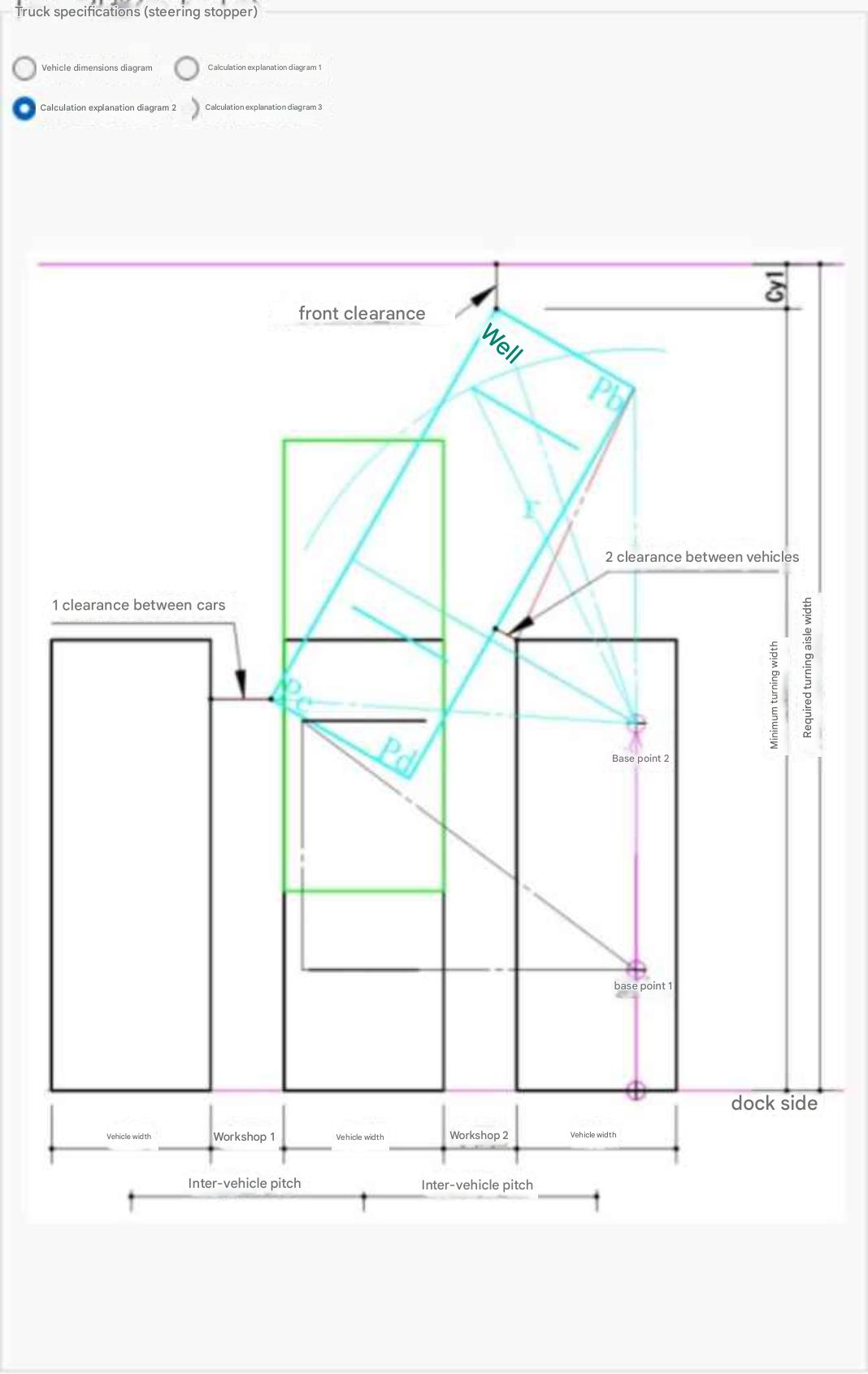
When a significant variance exists between Inter-Vehicle Clearance 1 and Clearance 2, execute simulations considering that the turning pivot center (Pivot Point 2) can be altered by vehicle shunting maneuvers.
Regarding forward clearance direction, design layout evaluations must account for surrounding environmental elements such as green belts, parking lots, and pedestrian walkways.
* Note: Turning swept path calculation features for articulated semi-trailers are scheduled for implementation in a future version update.
Section 1 Truck Turning Swept Path Simulation - Safe Design for Distribution Centers & Warehouses
A simulation utility designed for architects, site planners, and logistics engineers seeking to engineer safe and efficient dock bays within constrained site plot areas.
Easily simulates truck turning swept paths and required turning widths based on mathematical formulas from "Right-Angle Turning Swept Path Diagrams for Semi-Trailers and Full-Trailers" (JASO Z 006-92) published by the Society of Automotive Engineers of Japan (JSAE). Accommodates vehicle pitch adjustments matching distribution center loading bays and handles shifting turning centers via multi-point shunting maneuvers. Supports adding custom vehicle models via Excel (トラック寸法.xlsx) to assist practical trajectory engineering.
This utility provides intuitive execution of truck turning swept path calculations essential for distribution center and warehouse engineering.
- Flexible Vehicle Type Customization: Beyond default preset vehicle models, users can add or modify arbitrary vehicle dimensions by editing a dedicated Excel file (トラック寸法.xlsx).
- Practical Parameter Tuning: Adjust "Vehicle Pitch" and "Straight Run Values" matching site dock conditions to derive optimal required turning widths for field operations.
- Accommodating Operational Flexibility: When large variances exist between Clearance 1 and Clearance 2, simulations can model shifting the turning pivot center (Pivot Point 2) via multi-point shunting maneuvers.
- Supporting Safe Facility Design: Considers surrounding site conditions—such as forward clearance direction, green belt reserves, parking areas, and pedestrian walkways—as critical evaluation parameters.
Calculating inter-vehicle clearances utilizes trigonometric calculations on right-angled triangles (setting P1-P4 as adjacent base and P1-P3 as hypotenuse) to determine exact height offsets from turning angles. This enables highly accurate, mathematically grounded facility engineering.
Customizing Selectable Vehicle Types
Modifying or adding vehicle models is performed using "Tera計算Data\トラック軌跡計算\トラック寸法.xlsx".
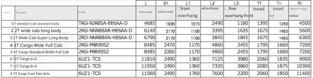
Simply select the target vehicle model from the calculation screen and click the "Start Calculation" button to execute the simulation.
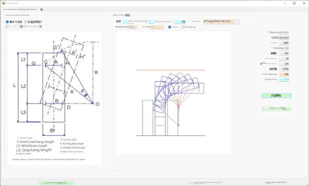
Simulating and Verifying Vehicle Pitch & Required Turning Width
Adjust vehicle pitch and straight run values to discover the required turning width suited to actual site conditions.
Deriving Inter-Vehicle Clearance 2 (Geometric Calculation Procedure)
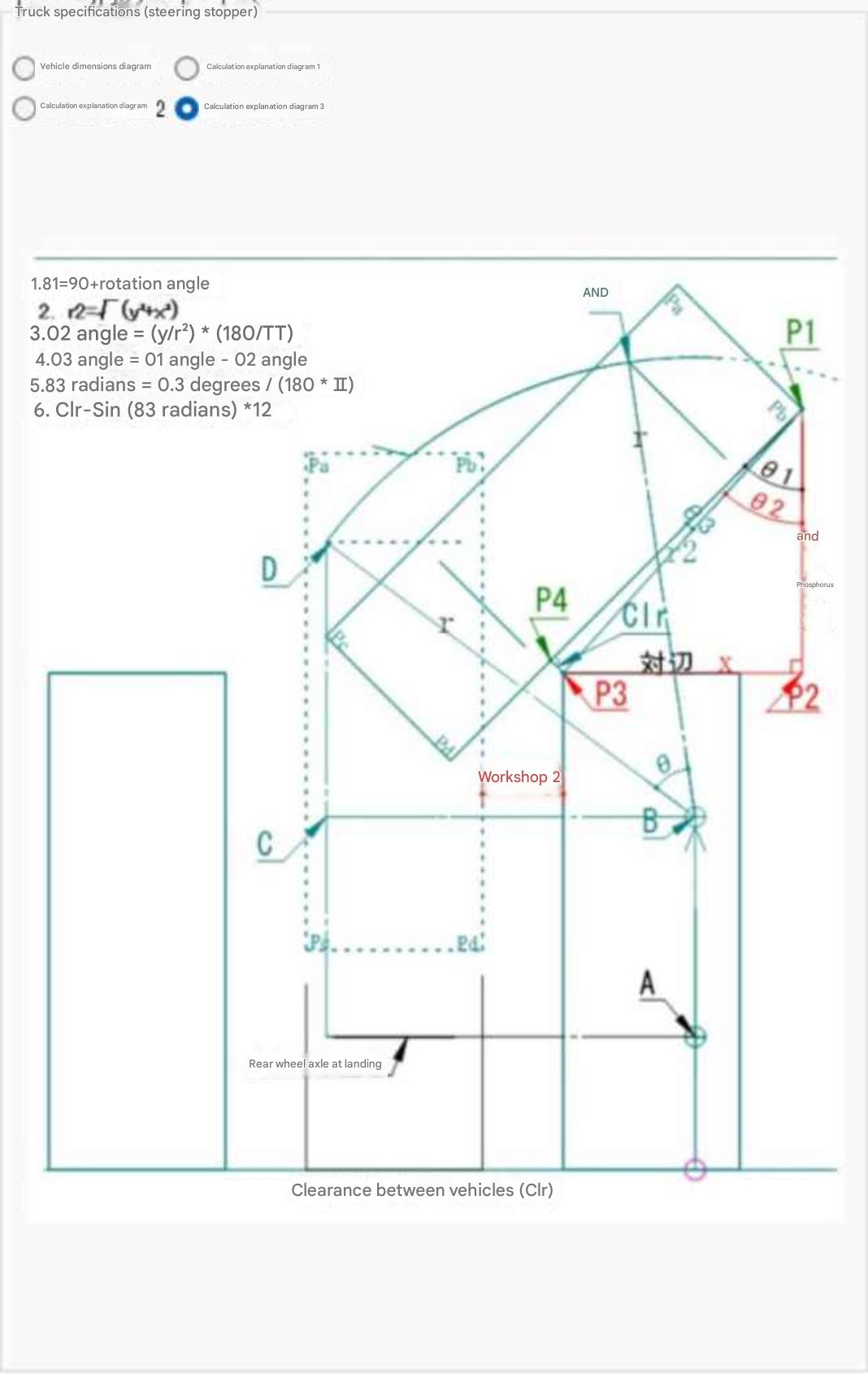
Accurate clearance values are derived using the following geometric mathematical approach:
- Define points P1 and P4 as the adjacent base side of a right-angled triangle.
- Define points P1 and P3 as the hypotenuse.
- Calculate the interior angle formed by vertices P4, P1, and P3.
- Using the calculated angle, solve for the vertical height distance from P4 to P3 via trigonometric functions.
- Using the solved height as a reference, verify safety clearance margins relative to adjacent parked vehicles.
- Based on calculation outcomes, finalize numerical dimensions required to guarantee safe turning trajectories.